- 您现在的位置:买卖IC网 > Sheet目录335 > ISL97636IRZ-TK (Intersil)IC LED DRIVR WHITE BCKLGT 24-QFN
�� �
�
�ISL97636�
�Inductor�
�The� selection� of� the� inductor� should� be� based� on� its�
�maximum� current� (I� SAT� )� characteristics,� power� dissipation�
�(DCR),� EMI� susceptibility� (shielded� vs� unshielded),� and� size.�
�Inductor� type� and� value� influence� many� key� parameters,�
�including� ripple� current,� current� limit,� efficiency,� transient�
�performance� and� stability.�
�Its� maximum� current� capability� must� be� adequate� to� handle�
�the� peak� current� at� the� worst� case� condition.� If� an� inductor�
�core� is� chosen� with� too� low� a� current� rating,� saturation� in� the�
�core� will� cause� the� effective� inductor� value� to� fall,� leading� to�
�an� increase� in� peak� to� average� current� level,� poor� efficiency�
�and� overheating� in� the� core.� The� series� resistance,� DCR,�
�within� the� inductor� causes� conduction� loss� and� heat�
�dissipation.� A� shielded� inductor� is� usually� more� suitable� for�
�EMI� susceptible� applications,� such� as� LED� backlighting.�
�The� peak� current� can� be� derived� from� the� fact� that� the�
�voltage� across� the� inductor� during� the� Off� period� can� be�
�shown� as:�
�IL� peak� =� (� V� O� ×� I� O� )� ?� (� 85%� ×� V� I� )� +� 1� ?� 2� [� V� I� ×� (� V� O� –� V� I� )� ?� (� L� ×� V� O� ×� f� S� )� ]�
�(EQ.� 9)�
�The� choice� of� 85%� is� just� an� average� term� for� the� efficiency�
�approximation.� The� first� term� is� average� current� that� is�
�inversely� proportional� to� the� input� voltage.� The� second� term�
�is� inductor� current� change� that� is� inversely� proportional� to� L�
�and� f� S� .� As� a� result,� for� a� given� switching� frequency� and�
�minimum� input� voltage� the� system� operates,� the� inductor�
�I� SAT� must� be� chosen� carefully.� At� a� given� inductor� size,�
�usually� the� larger� the� inductance,� the� higher� the� series�
�resistance� because� of� the� extra� winding� of� the� coil.� Thus� the�
�higher� the� inductance,� the� lower� the� peak� current� capability.�
�The� ISL97636� current� limit� may� also� have� to� be� taken� into�
�account.�
�Output� Capacitors�
�The� output� capacitor� acts� to� smooth� the� output� voltage� and�
�supplies� load� current� directly� during� the� conduction� phase� of�
�the� power� switch.� Output� ripple� voltage� consists� of� the�
�discharge� of� the� output� capacitor� for� I� LPEAK� during� FET� On�
�and� the� voltage� drop� due� to� flowing� through� the� ESR� of� the�
�output� capacitor.� The� ripple� voltage� can� be� shown� as:�
�backlight� applications� due� to� their� cost,� form� factor,� and� low�
�ESR.�
�A� larger� output� capacitor� will� also� ease� the� driver� response�
�during� PWM� dimming� Off� period� due� to� the� longer� sample�
�and� hold� effect� of� the� output� drooping.� The� driver� does� not�
�need� to� boost� harder� in� the� next� On� period� that� minimizes�
�transient� current.� The� output� capacitor� is� also� needed� for�
�compensation,� and� in� general,� 2x4.7μF/50V� ceramic�
�capacitors� are� suitable� for� the� notebook� display� backlight�
�applications.�
�Schottky� Diode�
�A� high� speed� rectifier� diode� is� necessary� to� prevent�
�excessive� voltage� overshoot,� especially� in� the� boost�
�configuration.� Low� forward� voltage� and� reverse� leakage�
�current� will� minimize� losses,� making� Schottky� diodes� the�
�preferred� choice.� Although� the� Schottky� diode� turns� on� only�
�during� the� boost� switch� Off� period,� it� carries� the� same� peak�
�current� as� the� inductor� ’s,� and� therefore,� a� suitable� current�
�rated� Schottky� diode� must� be� used.�
�Applications�
�High� Current� Applications�
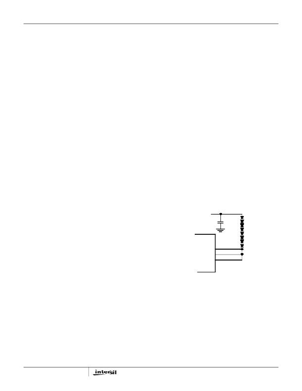
�Each� channel� of� the� ISL97636� can� support� up� to� 35mA.� For�
�applications� that� need� higher� current,� multiple� channels� can�
�be� grouped� to� achieve� the� desirable� current.� For� example,�
�the� cathode� of� the� last� LED� can� be� connected� to� IIN0� to� IIN2;�
�this� configuration� can� be� treated� as� a� single� string� with�
�105mA� current� driving� capability.�
�V� OUT�
�IIN0�
�IIN1�
�IIN2�
�FIGURE� 19.� GROUPING� MULTIPLE� CHANNELS� FOR� HIGH�
�Δ� V� CO� =� (� I� O� ?� C� O� ×� D� ?� f� S� )� +� (� (� I� O� ×� ESR� )�
�(EQ.� 10)�
�CURRENT� APPLICATIONS�
�The� conservation� of� charge� principle� in� Equation� 8� also�
�brings� up� a� fact� that� during� the� boost� switch� Off� period,� the�
�output� capacitor� is� charged� with� the� inductor� ripple� current�
�minus� a� relatively� small� output� current� in� boost� topology.� As�
�a� result,� the� user� needs� to� select� an� output� capacitor� with�
�low� ESD� and� with� a� enough� input� ripple� current� capability.�
�Output� Ripple�
�Δ� V� Co� can� be� reduced� by� increasing� C� O� or� f� S� ,� or� using� small�
�ESR� capacitors.� In� general,� ceramic� capacitors� are� the� best�
�choice� for� output� capacitors� in� small� to� medium� sized� LCD�
�15�
�Compensation�
�The� ISL97636� has� two� main� elements� in� the� system;� the�
�Current� Mode� Boost� Regulator� and� the� op� amp� based�
�multi-channel� current� sources.� The� ISL97636� incorporates� a�
�transconductance� amplifier� in� its� feedback� path� to� allow� the�
�user� some� levels� of� adjustment� on� the� transient� response�
�and� better� regulation.� The� ISL97636� uses� current� mode�
�control� architecture,� which� has� a� fast� current� sense� loop� and�
�a� slow� voltage� feedback� loop.� The� fast� current� feedback� loop�
�does� not� require� any� compensation.� The� slow� voltage� loop�
�must� be� compensated� for� stable� operation.� The�
�FN6570.0�
�May� 9,� 2008�
�发布紧急采购,3分钟左右您将得到回复。
相关PDF资料
ISL97671AIRZ
IC LED DVR PWM CTRL 6CH 20QFN
ISL97672AIRZ
IC LED DRVR LOW DIMMING 20QFN
ISL97672BIRZ
IC LED DRVR BACKLIGHT 20QFN
ISL97675IRZ-TK
IC LED DVR PWM CTRL 4CH 20QFN
ISL97677IRZ
IC LED DVR PWM CTRL 8CH 32QFN
ISL97678IRZ
IC LED DVR PWM DIMMING 8CH 32QFN
ISL97686IRTZ
IC LED DRVR BACKLIGHT 28TQFN
ISL97691IRTZ-TK
IC LED DRVR BACKLIGHT 3D 16TQFN
相关代理商/技术参数
ISL97642IRTZ
功能描述:IC REG TFT-LCD DC/DC 32-TQFN RoHS:是 类别:集成电路 (IC) >> PMIC - 电源管理 - 专用 系列:- 应用说明:Ultrasound Imaging Systems Application Note 产品培训模块:Lead (SnPb) Finish for COTS
Obsolescence Mitigation Program 标准包装:37 系列:- 应用:医疗用超声波成像,声纳 电流 - 电源:- 电源电压:2.37 V ~ 6 V 工作温度:0°C ~ 70°C 安装类型:表面贴装 封装/外壳:56-WFQFN 裸露焊盘 供应商设备封装:56-TQFN-EP(8x8) 包装:管件
ISL97642IRTZ-T
功能描述:IC REG TFT-LCD DC/DC 32-TQFN RoHS:是 类别:集成电路 (IC) >> PMIC - 电源管理 - 专用 系列:- 应用说明:Ultrasound Imaging Systems Application Note 产品培训模块:Lead (SnPb) Finish for COTS
Obsolescence Mitigation Program 标准包装:37 系列:- 应用:医疗用超声波成像,声纳 电流 - 电源:- 电源电压:2.37 V ~ 6 V 工作温度:0°C ~ 70°C 安装类型:表面贴装 封装/外壳:56-WFQFN 裸露焊盘 供应商设备封装:56-TQFN-EP(8x8) 包装:管件
ISL97642IRTZ-TK
功能描述:IC REG TFT-LCD DC/DC 32-TQFN RoHS:是 类别:集成电路 (IC) >> PMIC - 电源管理 - 专用 系列:- 应用说明:Ultrasound Imaging Systems Application Note 产品培训模块:Lead (SnPb) Finish for COTS
Obsolescence Mitigation Program 标准包装:37 系列:- 应用:医疗用超声波成像,声纳 电流 - 电源:- 电源电压:2.37 V ~ 6 V 工作温度:0°C ~ 70°C 安装类型:表面贴装 封装/外壳:56-WFQFN 裸露焊盘 供应商设备封装:56-TQFN-EP(8x8) 包装:管件
ISL97644IRZ
制造商:Rochester Electronics LLC 功能描述: 制造商:Intersil Corporation 功能描述:
ISL97644IRZ-T
功能描述:IC REG BOOST LDO VON VCOM 24-QFN RoHS:是 类别:集成电路 (IC) >> PMIC - 电源管理 - 专用 系列:- 应用说明:Ultrasound Imaging Systems Application Note 产品培训模块:Lead (SnPb) Finish for COTS
Obsolescence Mitigation Program 标准包装:37 系列:- 应用:医疗用超声波成像,声纳 电流 - 电源:- 电源电压:2.37 V ~ 6 V 工作温度:0°C ~ 70°C 安装类型:表面贴装 封装/外壳:56-WFQFN 裸露焊盘 供应商设备封装:56-TQFN-EP(8x8) 包装:管件
ISL97644IRZ-TK
功能描述:IC REG BOOST LDO VON VCOM 24-QFN RoHS:是 类别:集成电路 (IC) >> PMIC - 电源管理 - 专用 系列:- 应用说明:Ultrasound Imaging Systems Application Note 产品培训模块:Lead (SnPb) Finish for COTS
Obsolescence Mitigation Program 标准包装:37 系列:- 应用:医疗用超声波成像,声纳 电流 - 电源:- 电源电压:2.37 V ~ 6 V 工作温度:0°C ~ 70°C 安装类型:表面贴装 封装/外壳:56-WFQFN 裸露焊盘 供应商设备封装:56-TQFN-EP(8x8) 包装:管件
ISL97645AIRZ
功能描述:IC REG BOOST VON VCOM 24-QFN RoHS:是 类别:集成电路 (IC) >> PMIC - 电源管理 - 专用 系列:- 应用说明:Ultrasound Imaging Systems Application Note 产品培训模块:Lead (SnPb) Finish for COTS
Obsolescence Mitigation Program 标准包装:37 系列:- 应用:医疗用超声波成像,声纳 电流 - 电源:- 电源电压:2.37 V ~ 6 V 工作温度:0°C ~ 70°C 安装类型:表面贴装 封装/外壳:56-WFQFN 裸露焊盘 供应商设备封装:56-TQFN-EP(8x8) 包装:管件
ISL97645AIRZ-T
功能描述:IC REG BOOST VON VCOM 24-QFN RoHS:是 类别:集成电路 (IC) >> PMIC - 电源管理 - 专用 系列:- 应用说明:Ultrasound Imaging Systems Application Note 产品培训模块:Lead (SnPb) Finish for COTS
Obsolescence Mitigation Program 标准包装:37 系列:- 应用:医疗用超声波成像,声纳 电流 - 电源:- 电源电压:2.37 V ~ 6 V 工作温度:0°C ~ 70°C 安装类型:表面贴装 封装/外壳:56-WFQFN 裸露焊盘 供应商设备封装:56-TQFN-EP(8x8) 包装:管件